7.8. Underwater Loop Antenna
In the first world war, some submarines were equipped with radio signal receivers called “French” coils. An American submarine underwater at Long Island Sound received long-wave signals from Nauen, Germany in 1919 [59].
In 1941, Naval Research Laboratory presented a report which contains an investigation of a test that feasibility of receiving low frequency transmission signals while the receiving antennas completely submerged to the seawater. In order to determine this, it was necessary to make the following tests [30]:
- The signal strength and signal to noise ratio received by various types of antennas at various depths and for various frequencies.
- The best type of coupling device (input transformer and tuning unit) to transfer the received signals from the antennas to the receiver equipment.
Other tests to obtain other relevant information are as follows [30]:
- Underwater bearing of transmitter by null method.
- Q of loops.
- Effect of sea bottom on signals.
- Noise survey of ship.
In the report, some important results were highlighted [30]:
- The depth of the sea bottom seems to have practically no effect of the strength of the signals.
- Theoritical considerations of the design of a loop for underwater reception that a narrow loop with its long side parallel to the water surface is best.
- Signals of 1000 microvolts per meter in air should be readable to a depth of 10 meters (34 feet)(above loop) in ocean water and 11.5 meters (38 feet)(above loop) in water of less salinity.
In 1950, Toth and Fratianni investigated underwater loop reception and concluded that these results: a) Long-distance underwater radio receivers should be used in the range of 15-30 kHz and about maximum of 6 m (20 ft). b) A convenient underwater receiver system should be omnidirectional and at a certain distance from the water surface [59].
Induced voltage at the terminals of the antenna in the air is a function of the time of the frontwave that comes to the opposite edge of the coil that parallel to the electric vector. A similar induced voltage occurs at a loop antenna under water. However, since the wavelength of underwater wave propagation is much slower (1000 times slower than air) and the attenuation is too high, the phase differences of the induced voltages at the coil edges are high as shown in Fig. 7.1 [59].
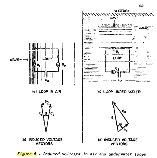
Fig. 7.1 : Induced voltages in air and underwater loops.
The operation of the loop antenna under water significantly increases the efficiency of receiving. For example, in a 20 kHz system, the output voltage increased by 1650 times or 64 dB. However, there are losses in the field strenght of about 66 dB. The loss of the output voltage is only about 2 dB in the transmissions from above the water surface to just below the water surface. Fig. 7.2 shows the amount of loss per foot under water [59].
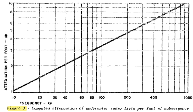
Fig. 7.2 : Computed attenuation of underwater radio field per foot of submergence.
In 1955, Fratianni investigated three experimental iron-cored omnidirectional loop antennas in regards to VLF signal reception. The aim of the investigation was to achive greater receiving efficiency with no increase in physical size, and weight, as compared to the Model AT-317 antenna which was employed on submarines at that time. They also noted that the interference effects of undesired radio signals were not changed by the presence of the Faraday shield. The experimental antennas were superior in pickup efficiency than the Model AT-317 antenna because of the greater winding areas and core lengths [21].
In 2011, Waheed-uz-Zaman and Yousufzai presented a study about a VLF transmitting antennas for submerged submarines [61].