3.6. Signal to Noise Ratio (SNR)
The minimum signal that can produce a useful output from a radio receiver is determined by the output signal-to-noise ratio [CIA, 1957].
| Externally Generated | Internally Generated |
|---|---|
| Atmospheric (electrical storms) | Antenna ohmic resistance (thermal) |
| Cosmic (extra-terrestrial radiation) | Coupling circuit resistance (thermal) |
| Man-made static | First amplifier or mixer (short noise) |
| Precipitation static | |
| Radiation resistance (thermal) |
Belrose gives the SNR formula of a loaded-loop antenna [1]:
where \(E\) is the field strength, \(L\) is loop inductance, \(N\) is number of turns, \(Q\) is the loaded \(Q\) of the loop, \(\mu_{rod}\) is the permeability of the rod, \(b\) is the receiver bandwidth, and \(A\) is the loop area.
Note
Higher sensitivity can also be obtained (especially at frequencies below 500 kHz) by bunching ferrite cores together to increase the loop area over that which would be possible with a single rod [1].
3.6.1. Rx
Laurent and Carvalho gave the signal to noise ratio of a receiving [Laurent and Carvalho, 1962].
- E magnitude of the electric field intensity vector
- m modulation index
- A_r area of the rod
- C total tuning capacitance
- omega_0 resonance frequency
- Q_L=omega_0frac{R_pR_L}{R_p+R_L}C
- K=1.38{10}^{-23} Boltzmann’s constant [Joules/Kelvin]
- T Temperature in degrees Kelvin
- Delta f 3 db bandwidth of the device
- mu_c=L_2/L_1 coefficient of change in inductance when the rod is inserted
- F form factor (geometry of the coil)
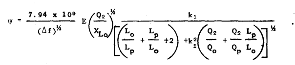
Fratianni obtained the optimum signal to noise ratio equation for a transformer coupled loop system and direct coupled loop system[Fratianni, 1948]

3.6.3. Direct Connected
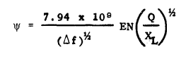
Fig. 3.6 : ex18.
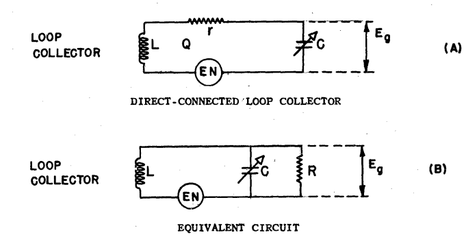
Fig. 3.7 : snr-direct-connected.
- Lp: primary inductance
- Lo: loop inductance
- K1: coupling coefficient of transformer
- Q0: q value of loop
- Qp: q value of primary
- Q2: q value of secondary
- Delta f: the width in cps of the equivalent rectangle having the same area as the squared transmission characteristic of the input circuit
- XL0: reactance of loop
- E: loop induced voltage