5.7. Impedance Matching
The impedance in the antenna’s main RLC circuit is not well matched to 50 \(\Omega\). The induced voltage is highly reflected if connected directly to a 50 \(\Omega\) input. One way to improve the matching is to use a secondary coil or a so called pick-up coil next to the main coil [Koskimaa, 2016].
5.7.1. Pick-up Coil
The pick-up coil will act as an impedance transformer. The impedance transformer transforms the main coil impedance and voltage into the secondary coil according to the equation
When the pick-up works as intended the output voltage from the decreased secondary coil voltage is still higher than the original main coil output voltage due to the improved matching.
When inductors are coupled a current change in one inductor induces a voltage in the second inductor. The mutual inductance between the inductors is defined as
where k is the coupling coefficient. The equivalent circuit of two coupled inductors is a T-circuit shown in figure below.
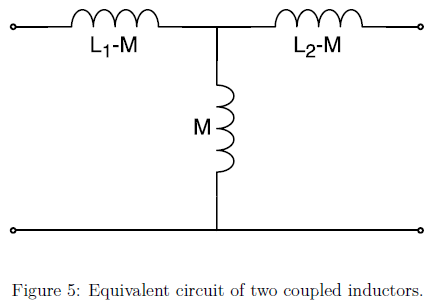
Fig. 5.17 : Equivalent circuit of two coupled inductors.
The voltage over the two coils can be expressed with the mutual inductance as the following:
The coupling coefficient of the two coils can be measured by changing the secondary coil from open circuit to shorted and observing the change in the resonant frequency. When the second coil is shorted the voltage in the secondary coil becomes zero and the current will be
By inserting this into the voltage equation of the primary coil in equation U1_U2
where L_s is the apparent/measured inductance over the primary coil when the secondary coil is shorted. Now the mutual inductance squared can be written as
Using this the coupling coefficient becomes
where f_0 and f_s are the resonance frequencies related to the inductances L_1 and L_s according to resonance frequency of the RLC with the secondary coil open and shorted, respectively.
The impedance at the antenna output is Z_2. A portion of the pick-up voltage U_2 is reflected at the antenna output according to equation
where the load impedance is 50 \(\Omega\). The output voltage of the antenna is [Koskimaa, 2016]
5.7.2. Transformer Coupling
Bachman investigated a low-impedance loop with coupling transformer and explained the transformer parameters in terms of the circuit and transformer coupling coefficients in 1945. The gain of the transformer coupled loop system was analysed. The low-impedance transformer-coupled loop and a high-impedance loop connected directly to the same tuning capacitor was compared. He concluded that an ideal transformer-coupled loop has 38.4% of the gain from a direct-connected loop of the same area, assuming the same Q in the transformer secondary as in the direct connected loop. In Fig. 5.18 the low-impedance loop coupling-transformer circuit was shown [6].
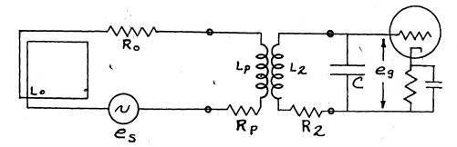
Fig. 5.18 : Low-impedance loop coupling-transformer circuit.
In 1948 Fratianni investigated methods of coupling loops to receivers that transformer-coupled and direct connected as shown in Fig. 5.19. Mathematical analysis and theoritical treatment of transformer-coupled was done. Coupling design for maximum voltage amplification and optimum signal-to-noise ratio was studied. In order to show the effects of parameters on circuit performance eight conditions were built. All direct coupled cases were better than transformer-coupled cases with regard to signal-to-noise ratio. Only two transformer-coupled sets better than direct coupled sets for voltage amplification basis. He also noted that if a long cable length was required, transformer-coupled circuits could be preferred [20].
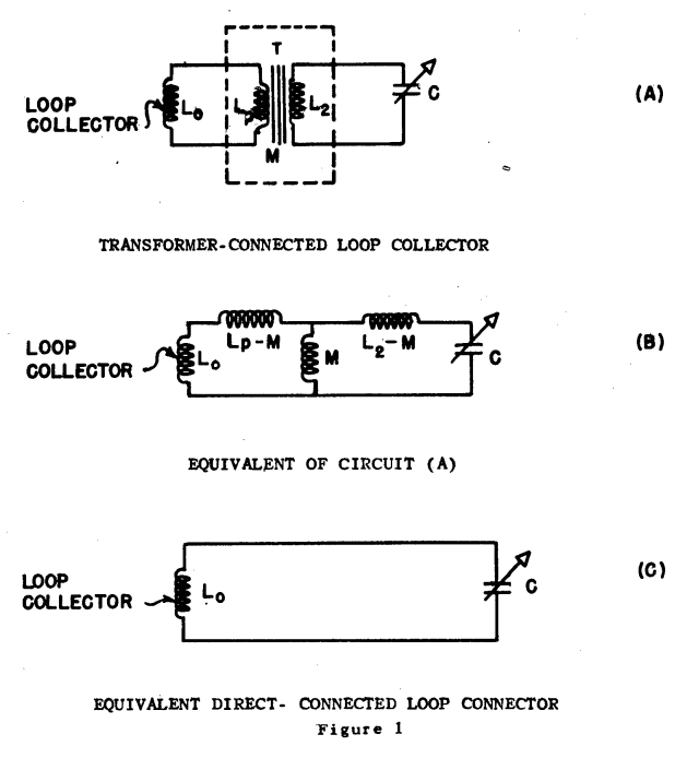
Fig. 5.19 : Transformer-coupled and direct connected receiving loops.